The Creation of Quadjet
This past fall, I took a class called 2.017 - Design of Electromechanical Robotic Systems. This class was almost entirely a project based class where we formed groups of students and chose to work on a project of our own conception.
My group had the idea to make a model platform version of the Flyboard jetpack concept. http://rockymountainflyboard.com/
Our concept, much like the Flyboards, was a docked station containing the system's pumps. Controlling the throughput of these pumps would enable us to control the output lift from each of the Quadjet's nozzles and enable us to control the craft.
Proposed Quadjet Control Schematic

The biggest initial question with our concept was, will there be too much of a delay between our controlling pressure differential at the pumps and the output force at the craft's nozzles. I was in charge of figuring out if this delay would be an issue in our control scheme.
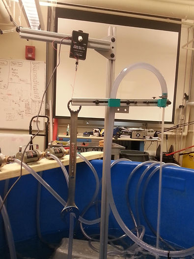
To measure the control delay of our pump, tubing nozzle system I developed a testing mechanism (seen on the left) that mimicked the configuration of one tube of the Quadjet. In this simplified setup I was able to measure the force produced by a single nozzle at various control voltages.
I controlled the pump with an arduino through a motor controller (see below) For measuring the system I used a Venier Force Probe nozzle's output force and a voltage probe to record the motor controller's output voltage.

Since it was my goal to determine the delay between the control voltage and the ouput force, I needed to develop a mechanism for measuring the time it took for the system to reach an equilibrium and a certain control voltage. I ran a number of tests with my testing setup. The most conclusive test was a step input voltage with a range of different max step-height values.
Running this series of input step voltages of different magnitudes, (seen on the right) I measured the resulting force at the nozzles and the delay between the input control voltage and the measured force output.

As seen on the right, the control delay (time it took the system to regain equilibrium after each step of control input) was about 0.15 seconds for a setup with six feet of tubing between the pump and the nozzle.
This delay was small enough that it gave us hope that our control scheme would work but our final design would need significantly more than six feet of tubing and would adding more tubing significantly increase the delay?

To test the effect of tubing on the delay I ran the step input tests again with twenty-five feet of tubing to see if there was a significant increase in the delay. Though I more than quadrupled the length of tubing, the control delay only increased a twentieth of a second to about 0.20 seconds.
The small increase in delay between six and twenty-five feet of tubing implied that the delay between control voltage and nozzle output of force is not significantly affected by the length of tubing between the pump and the nozzle but is more likely due to delay in the pump itself.

Having validated that our control scheme was sufficiently responsive to be able to stabilize our craft, we continued to build.
We had three main design concepts, a stiff pvc frame and a flexible tube frame version. In preliminary tests and reasoning we determined that the stiff frame created unnecessary amount of viscous friction with its tight corners and abrupt turns. The stiff frame being eliminated we continued with the flexible tube concept.


With a few more modifications we settled on our final design. A light, cross supported base holding four flexible tubes ending in four 1/4-inch nozzles.

Proceeding with the flexible tube design we had a lot of success and proceeded to create a control system based on input from an IMU seated in the center of the hovercraft portion of our design.
 Quadjet ConstrainedQuadjet constrained to a plane with rotation for early controller testing. |  Quad PumpsThe four pumps by which the Quadjet is powered and controlled. |  Quad TubingTwenty-five feet of tubing between our hover craft and the pump station. Will allow for ~twenty foot radius of movement. |
|---|
 Quad ElectronicsThe brains of the Quadjet: one Arduino Mega, four motor controllers and some snazzy wiring. |  Quad Pump BoxFinal pump containment structure for the Quadjet. The four pumps contained in the box suck water in tubing at one end of the box and push pressurized water out the other end. This pressurized water is what propels the quadjet. |
|---|
Early flight test in a tank in lab.
Final testing in the Charles River!